Thank you so much for your involvement with the Owner's Club Forum! We hope you've gotten some great information and had the chance to interact with other owners on the current system.
I guess the next step is to replace the sender
Options

pbolden
Member Posts: 45 ✭✭
Hello everyone,
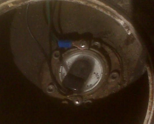
I guess the next step is to replace the sender. As you can see in the pic, the sender has a manual gauge on top. The manual gauge works fine so I guess that the float is okay, the gauge at the helm is not (as it jumps back and forth).
Questions:
Are the 2 black wires coming out of the black cap on top of the gauge sending wires and are they both connected to the gauge at the helm?
How do I remove the black cap? Do I pry it off, pull it off, twist it off?
Are those allen screws holding the sender to the fuel tank?
I am having difficulty finding online information specific to marine sender installation. I also can’t find a sender with the manual gauge on top. Is that none of them come with a manual gauge and you must attach a conversion capsule on top of the sender?
Thanks,
Paul Bolden
United States Coast Guard Aux, VFC, FSO-VE
Comments
-
Wow Paul, I know that this is of little help but that may qualify for the most unusual sending unit design I've ever seen. And maybe one of the most inconvenient to replace as well. From what I see in your picture, it looks like it has rivets holding the unit in place (which means drilling them out, then what?). It's like they designed it never expecting to replace it. Usually the top of sending units are pretty easy to remove and service as long as you have easy access to them. Any idea what that bracket is fastened to the face of the gauge, what it's for and why (maybe I'm missing something from the picture)? I may be the only one scratching my head, but I doubt it. Maybe this warrants a trip to the dealer just to find out what you're up against.2012 SD237 I/O Mercruiser 5.0L MPI ECT/ Bravo 32012 Load Rite Elite Tandem axle trailer
-
Hi cjjjdeck,
I haven't seen anything like it either and haven't found anything online to replace it. I was also wondering about that bracket as well. Allens or rivets, I don't know. None of my allens were getting a bite though I didn't try very hard. When I saw the odd configuration I decided to check here first before doing anything else. I didn't want to damage anything as the manual gauge that is sitting on top of the sender is working fine, its the gauge at the helm that is erratic. While its a little bit of a hassle removing the access port to check the fuel level it does give me a way to know the fuel level until I get this issue resolved.
Paul Bolden
United States Coast Guard Aux, VFC, FSO-VE -
I think I figured this out. My boat has a mechanical sender originally equipped with a "Direct Site Gauge." The direct site gauge was replaced (probably by hurricane) with a conversion capsule which converts the fuel level reading from a standard direct site gauge to electric dash-mounted gauge (33-240 Ohms). Here's a pic of a Moeller conversion capsule.
Can anyone confirm this theory?
Paul Bolden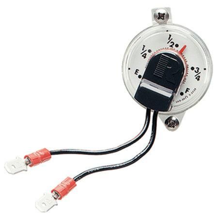
United States Coast Guard Aux, VFC, FSO-VE -
Paul, the Black wires are the power to/from the sender conversion capsule. The sender, like most others, is just a resistor in-line between the battery and the gauge. The green wire is the ground or Battery(-). More than likely, the problem is the sender capsule vs. the gauge. To test this theory, follow these steps:- Only the positive accessory (Purple wire) wire from the engine harness is connected to the IGN or I Terminal on the gauge.
- The negative or ground terminal of the gauge is connected to the boats grounding system.
- The S or Sender terminal is connected to the Fuel tank sender.
- The fuel tank must also have a connection to the boats grounding system
- After insuring that your wiring between the fuel sender on the tank and the connections on the fuel gauge are correct.
- Turn the Ign Key to "ON" and Using a jumper wire, ground the center or S terminal on the fuel sender at the tank
- If your fuel gauge jumps to the FULL reading, the problem is in the fuel tank sender.
- If your fuel gauge does not move, proceed to the next step.
- Using a test light, with the key in the on position.
- Check for power at the I or Ignition terminal on the gauge.
- If Power is "ON" at gauge terminal, ground "S" terminal and "G" terminal and check gauge reading. If reading moves to full then you have a wiring problem between gauge and sender,otherwise gauge is defective.
- If the power is "OFF" at the gauge terminal, check for ground by connecting tester to Ignition switch "RED" terminal and to the "G" Terminal on the gauge. If the ground is good, use a jumper to power gauge "I" terminal and retest gauge.
- Once problem has been diagnosed properly, repair as required.
- To replace fuel sender, clean area thoroughly and remove the six screws around the sender that secure it to the tank
- Remove the sender and set aside
- Measure the tank depth for proper sender recognition. There are two lenghts of senders generally used and you must purchase the correct one.
- Follow the instructions provided with the sender when setting the depth.
- After sender installation is complete, check ground wire on the tank that attaches to the boats battery negative terminal or to the boats grounding system.
- If wiring needs to be replaced. Use the standard wiring color codes as follows:
- Fuel Sender "S" terminal wire is "Pink"
- All grounds are "Black" wire.
- The "I" Terminal wire, between gauge and key switch is "Purple".
- When ever possible use "Tinned Primary" wire of 14ga for fuel system wiring.
Rob Castle
2001 Hurricane GS201 FD
Yamaha 150 V6 2 Stroke, Oil Injection -
Thanks rdcastle for the great detail in your response, I appreciate the time that you took. Before doing your tests, my questions are these:
The gauge on the sending unit is working fine. The gauge at the helm is not. Does this tell me anything?
Assuming that it is a conversion capsule on top of the sending unit and since the gauge on top of the sending unit is working, don't I only need to replace the conversion capsule which is held on by 2 screws?
Thanks,
Paul Boldenconversion capsuleconversion capsuleconversion capsule
United States Coast Guard Aux, VFC, FSO-VE